Non Digital Systems Use a Continuous Range of Values to Represent Information
Contributors: jimblom
Overview
We live in an analog world. There are an infinite amount of colors to paint an object (even if the difference is indiscernible to our eye), there are an infinite number of tones we can hear, and there are an infinite number of smells we can smell. The common theme among all of these analog signals is their infinite possibilities.
Digital signals and objects deal in the realm of the discrete or finite, meaning there is a limited set of values they can be. That could mean just two total possible values, 255, 4,294,967,296, or anything as long as it's not ∞ (infinity).
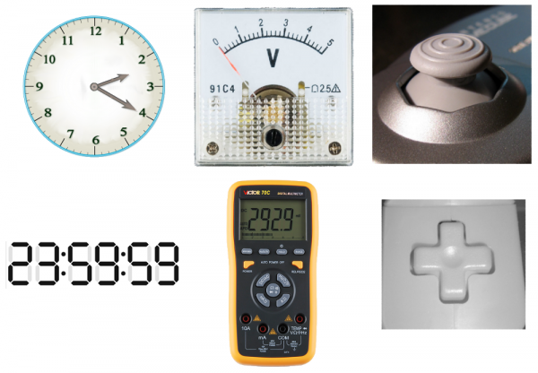
Real-world objects can display data, gather inputs by either analog or digital means. (From left to right): Clocks, multimeters, and joysticks can all take either form (analog above, digital below).
Working with electronics means dealing with both analog and digital signals, inputs and outputs. Our electronics projects have to interact with the real, analog world in some way, but most of our microprocessors, computers, and logic units are purely digital components. These two types of signals are like different electronic languages; some electronics components are bi-lingual, others can only understand and speak one of the two.
In this tutorial, we'll cover the basics of both digital and analog signals, including examples of each. We'll also talk about analog and digital circuits, and components.
Suggested Reading
The concepts of analog and digital stand on their own, and don't require a lot of previous electronics knowledge. That said, if you haven't already, you should peek through some of these tutorials:
- Voltage, Current, Resistance and Ohm's Law
- What is a Circuit
- And some mathematics concepts: reading graphs, and understanding the difference between finite and infinite sets.
Analog Signals
Define: Signals
Before going too much further, we should talk a bit about what a signal actually is, electronic signals specifically (as opposed to traffic signals, albums by the ultimate power-trio, or a general means for communication). The signals we're talking about are time-varying "quantities" which convey some sort of information. In electrical engineering the quantity that's time-varying is usually voltage (if not that, then usually current). So when we talk about signals, just think of them as a voltage that's changing over time.
Signals are passed between devices in order to send and receive information, which might be video, audio, or some sort of encoded data. Usually the signals are transmitted through wires, but they could also pass through the air via radio frequency (RF) waves. Audio signals, for example might be transferred between your computer's audio card and speakers, while data signals might be passed through the air between a tablet and a WiFi router.
Analog Signal Graphs
Because a signal varies over time, it's helpful to plot it on a graph where time is plotted on the horizontal, x-axis, and voltage on the vertical, y-axis. Looking at a graph of a signal is usually the easiest way to identify if it's analog or digital; a time-versus-voltage graph of an analog signal should be smooth and continuous.
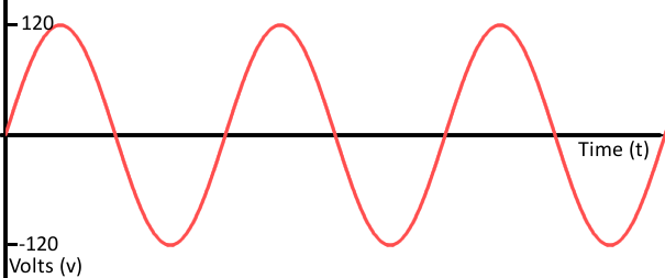
While these signals may be limited to a range of maximum and minimum values, there are still an infinite number of possible values within that range. For example, the analog voltage coming out of your wall socket might be clamped between -120V and +120V, but, as you increase the resolution more and more, you discover an infinite number of values that the signal can actually be (like 64.4V, 64.42V, 64.424V, and infinite, increasingly precise values).
Example Analog Signals
Video and audio transmissions are often transferred or recorded using analog signals. The composite video coming out of an old RCA jack, for example, is a coded analog signal usually ranging between 0 and 1.073V. Tiny changes in the signal have a huge effect on the color or location of the video.
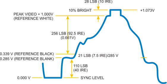
An analog signal representing one line of composite video data.
Pure audio signals are also analog. The signal that comes out of a microphone is full of analog frequencies and harmonics, which combine to make beautiful music.
Digital Signals
Digital signals must have a finite set of possible values. The number of values in the set can be anywhere between two and a-very-large-number-that's-not-infinity. Most commonly digital signals will be one of two values -- like either 0V or 5V. Timing graphs of these signals look like square waves.
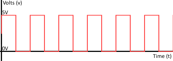
Or a digital signal might be a discrete representation of an analog waveform. Viewed from afar, the wave function below may seem smooth and analog, but when you look closely there are tiny discrete steps as the signal tries to approximate values:
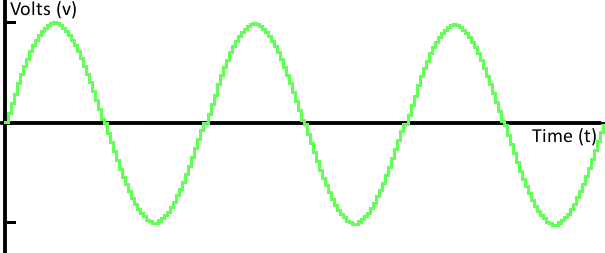
That's the big difference between analog and digital waves. Analog waves are smooth and continuous, digital waves are stepping, square, and discrete.
Example Digital Signals
Not all audio and video signals are analog. Standardized signals like HDMI for video (and audio) and MIDI, I2S, or AC'97 for audio are all digitally transmitted.
Most communication between integrated circuits is digital. Interfaces like serial, I2C, and SPI all transmit data via a coded sequence of square waves.
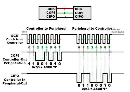
Serial peripheral interface (SPI) uses many digital signals to transmit data between devices.
Analog and Digital Circuits
Analog Electronics
Most of the fundamental electronic components -- resistors, capacitors, inductors, diodes, transistors, and operational amplifiers -- are all inherently analog. Circuits built with a combination of solely these components are usually analog.
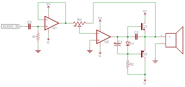
Analog circuits are usually complex combinations of op amps, resistors, caps, and other foundational electronic components. This is an example of a class B analog audio amplifier.
Analog circuits can be very elegant designs with many components, or they can be very simple, like two resistors combining to make a voltage divider. In general, though, analog circuits are much more difficult to design than those which accomplish the same task digitally. It takes a special kind of analog circuit wizard to design an analog radio receiver, or an analog battery charger; digital components exist to make those designs much simpler.
Analog circuits are usually much more susceptible to noise (small, undesired variations in voltage). Small changes in the voltage level of an analog signal may produce significant errors when being processed.
Digital Electronics
Digital circuits operate using digital, discrete signals. These circuits are usually made of a combination of transistors and logic gates and, at higher levels, microcontrollers or other computing chips. Most processors, whether they're big beefy processors in your computer, or tiny little microcontrollers, operate in the digital realm.
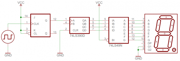
Digital circuits make use of components like logic gates, or more complicated digital ICs (usually represented by rectangles with labeled pins extending from them).
Digital circuits usually use a binary scheme for digital signaling. These systems assign two different voltages as two different logic levels -- a high voltage (usually 5V, 3.3V, or 1.8V) represents one value and a low voltage (usually 0V) represents the other.
Although digital circuits are generally easier to design, they do tend to be a bit more expensive than an equally tasked analog circuit.
Analog and Digital Combined
It's not rare to see a mixture of analog and digital components in a circuit. Although microcontrollers are usually digital beasts, they often have internal circuitry which enables them to interface with analog circuitry (analog-to-digital converters, pulse-width modulation, and digital-to-analog converters. An analog-to-digital converter (ADC) allows a microcontroller to connect to an analog sensor (like photocells or temperature sensors), to read in an analog voltage. The less common digital-to-analog converter allows a microcontroller to produce analog voltages, which is handy when it needs to make sound.
Resources and Going Further
Now that you know the difference between analog and digital signals, we'd suggest checking out the Analog to Digital Conversion tutorial. Working with microcontrollers, or really any logic-based electronics, means working in the digital realm most of the time. If you want to sense light, temperature, or interface a microcontroller with a variety of other analog sensors, you'll need to know how to convert the analog voltage they produce into a digital value.
Also, consider reading our Pulse Width Modulation (PWM) tutorial. PWM is a trick microcontrollers can use to make a digital signal appear to be analog.
Here are some other subjects which deal heavily with digital interfaces:
- Binary
- Logic Levels
- Serial Communication
- SPI Communication
- I2C Communication
- IR Communication
Or, if you'd like to delve further into the analog realm, consider checking out these tutorials:
- Voltage Dividers
- Resistors
- Diodes
- Capacitors
- Transistors
martinforbeartne1998.blogspot.com
Source: https://learn.sparkfun.com/tutorials/analog-vs-digital/all
0 Response to "Non Digital Systems Use a Continuous Range of Values to Represent Information"
Post a Comment